Ross Clark Circle Bridge
Thompson Engineering & Forterra

Location:
Alabama DOT
Dothan, AL 36301
Schedule:
Project Start Date: 2/9/2015
Project Completion Date: 5/26/2016
Precast erected in 7 days
Cost:
Total Project Cost: $2.43 million
Square Footage: 120 ft long
Involved Companies
Precast Concrete Producer
Forterra
380 Industrial Park Drive
Pelham, AL 35124
https://forterrabp.com/
Engineer of Record
Thompson Engineering
2970 Cottage Hill Road
Mobile, AL 36606
http://thompsonengineering.com/
General Contractor
McInnis Construction
260 Commerce Street
Montgomery, AL 36104
http://mcinnisconstructs.com/
Material Supplier
Hilman Rollers
12 Timber Lane
Marlboro, NJ 07746
https://www.hilmanrollers.com/
Background text via ASPIRE Fall 2016 article
Ross Clark Circle is a divided four-lane highway carrying State Route (SR) 210 that coincides with U.S. Highway 231 in a circle around Dothan, Ala., in the southeastern corner of the state. Originally constructed in the 1950s, Ross Clark Circle has seen average daily traffic increase from 5000 vehicles per day to approximately 40,000 vehicles per day and is expected to exceed 73,000 vehicles per day in 20 years.
On the west side of the city, Ross Clark Circle crosses Beaver Creek supported by a triple-barrel, 6-ft-rise-by-10-ft-span cast-in-place concrete box culvert. This culvert, under 18 ft of fill, had serious cracking and was slated for replacement in a consultant’s original contract plans to widen Ross Clark Circle from four to six lanes.
rendering of new bridge over culvert
The decision to replace the culvert with another was made by the state’s bridge hydraulics engineer during his site evaluation and was based on the culvert’s drainage history. Much development has occurred inside Ross Clark Circle without regard to water runoff or detention. This has resulted in complete immersion of the opening with upstream flooding in severe rain events because the culvert was not designed to carry the increased flow of the creek.
Changing anything with regard to the culvert’s cross-sectional drainage area had the potential to change downstream drainage characteristics, which could result in legal liability and civil lawsuits against the state. A culvert the same size as the existing one had to be used in that location.
Going with a new box culvert was easier said than done. In order to accommodate the additional roadway width and a 3:1 backslope, the culvert had to be lengthened 25 ft at one end and 30 ft at the other. Above-ground water and sewer pipes at both ends within those ranges prohibited this approach. The next plan was to consider building a shorter culvert with a retaining wall running over the ends. This idea was not considered feasible due to settlement and cost issues. In addition to these problems, the culvert would have had to be built in two stages—half the culvert length at a time with traffic shifts.
Typical section for northbound bridge via ALDOT
Typical section for southbound bridge via ALDOT
details of jacking bays between girders in semi-integral abutment diaphragm via aldot
To do this, the contractor would have to drive sheet piles on both sides of the culvert for soil retention and then drive unembedded sheet piles over the culvert. These unembedded sheet piles would have had to be supported laterally with whalers, which would then have had to be secured to sets of nested piles driven on both sides of the culvert.
After stage one completion, the sheet piles and the nested piles would have had to be pulled and redriven and the whalers reattached at least 10 ft away to allow for construction of stage two. The perceived cost and constructability issues presented serious obstacles to moving forward.
When Alabama Department of Transportation (ALDOT) structural engineers were presented this scenario, they recognized the opportunity to apply an accelerated bridge construction (ABC) innovation as the solution.
They determined that although the culvert was cracked, the cracks could be corrected and the culvert could continue to carry water without further concern if traffic and a substantial amount of dead load were removed. This could be accomplished by constructing two bridges over the culvert, maintaining the same roadway grade, and then removing half the fill over the culvert.
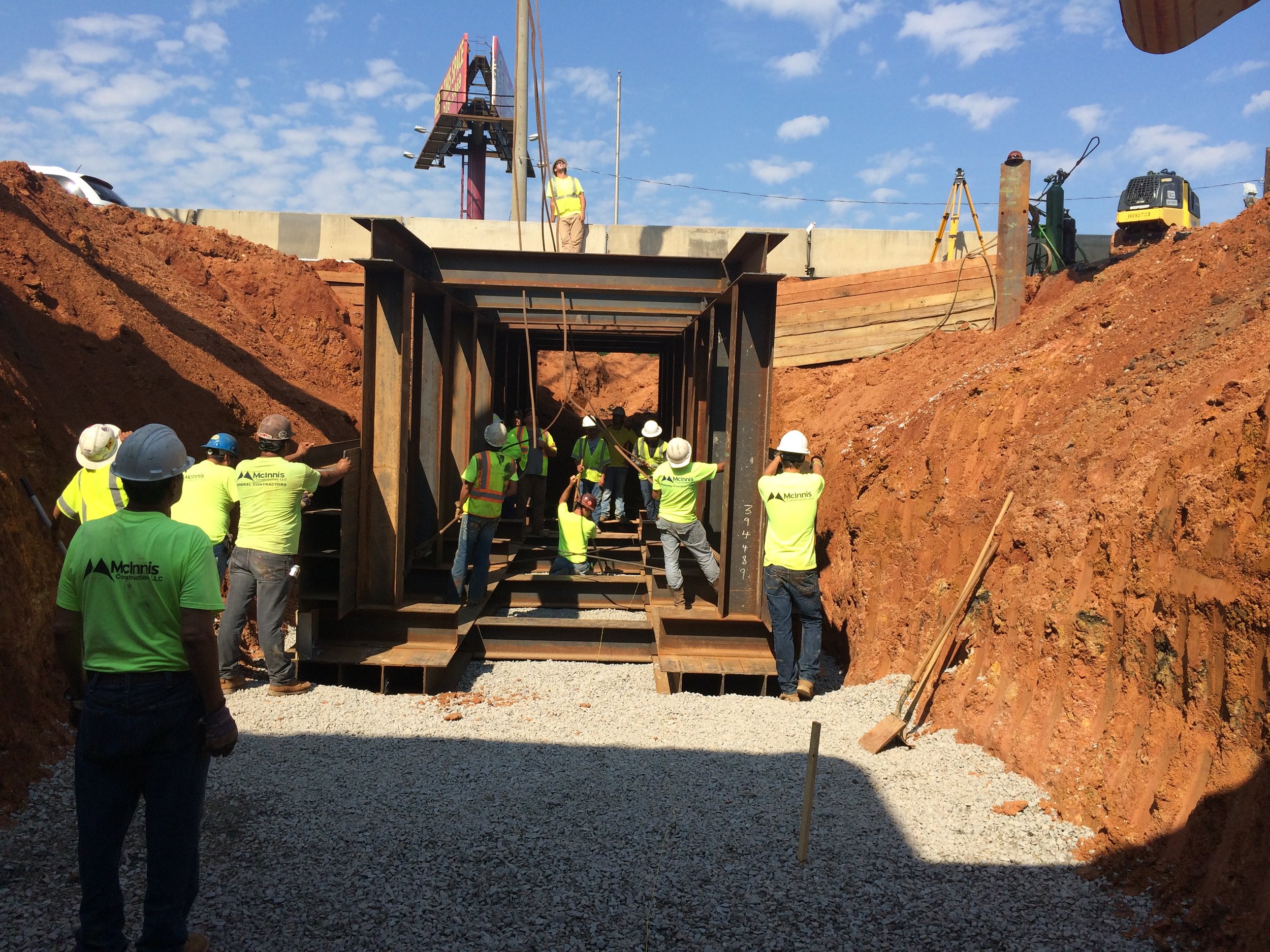
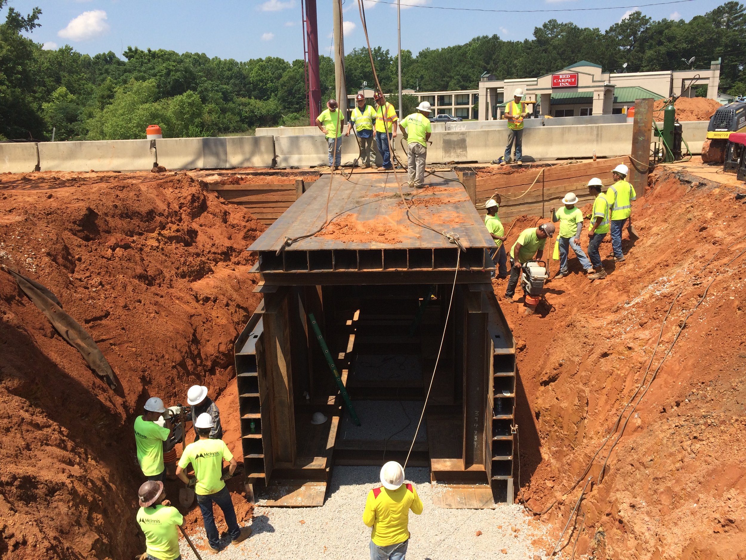
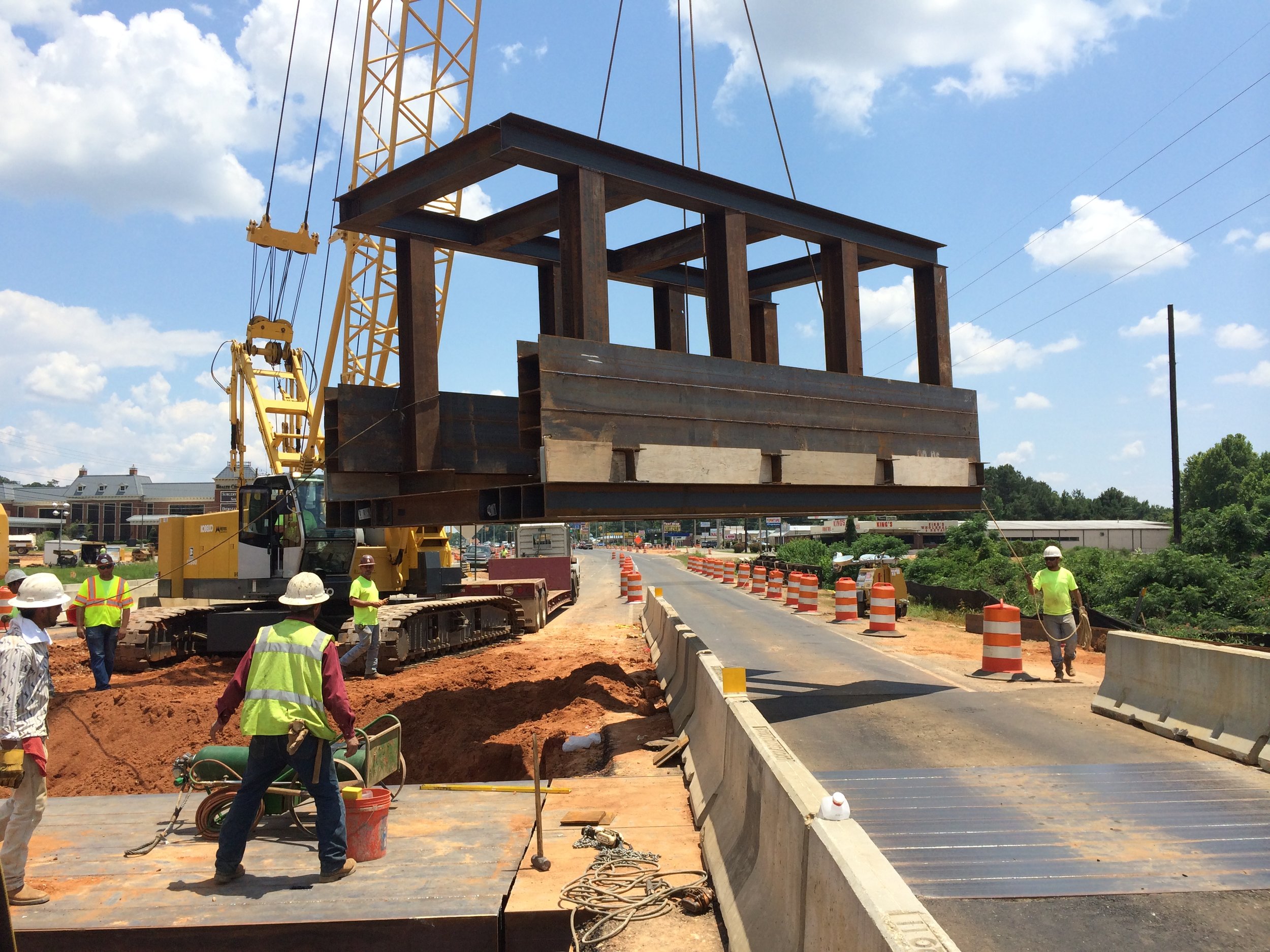
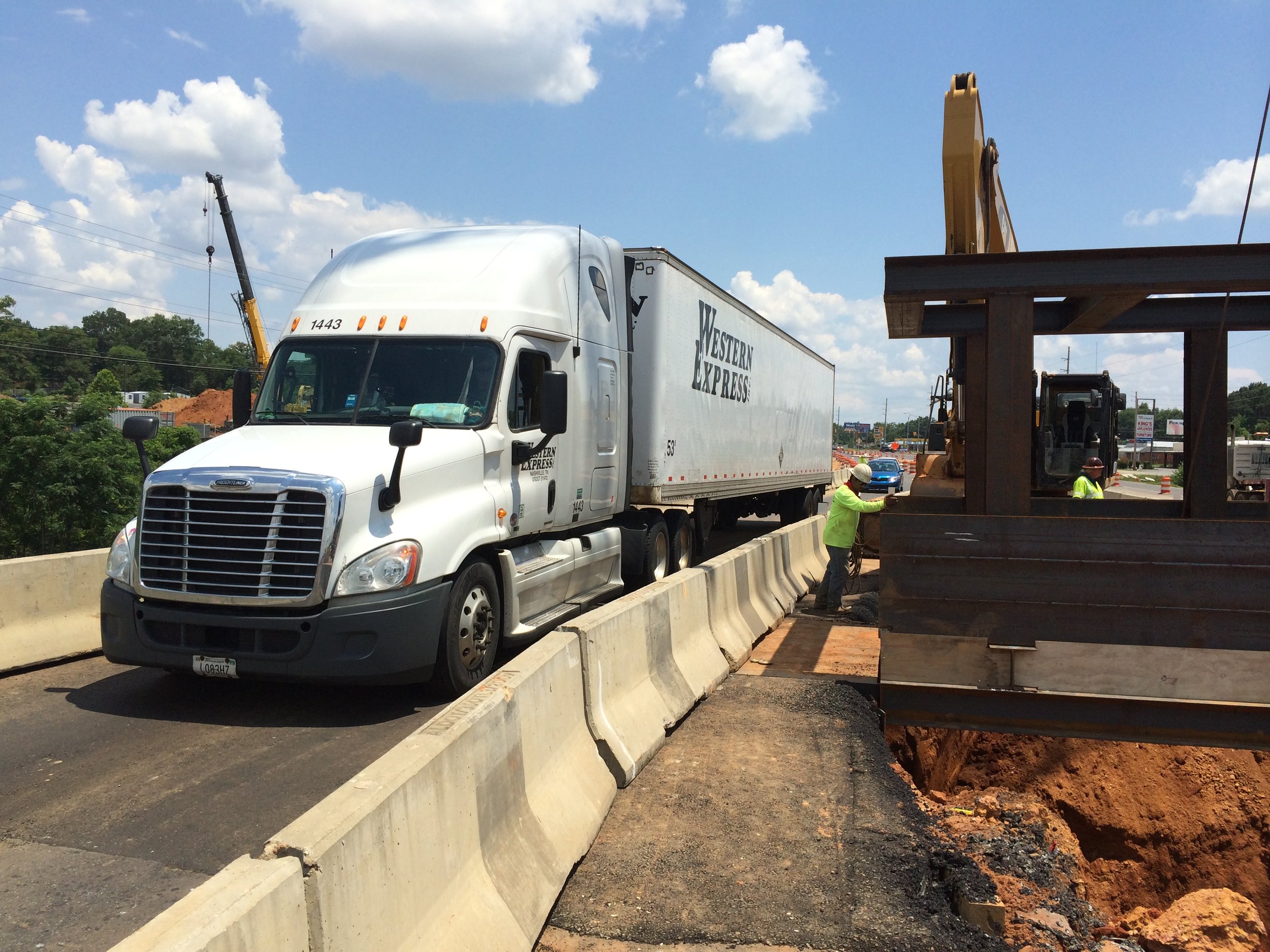
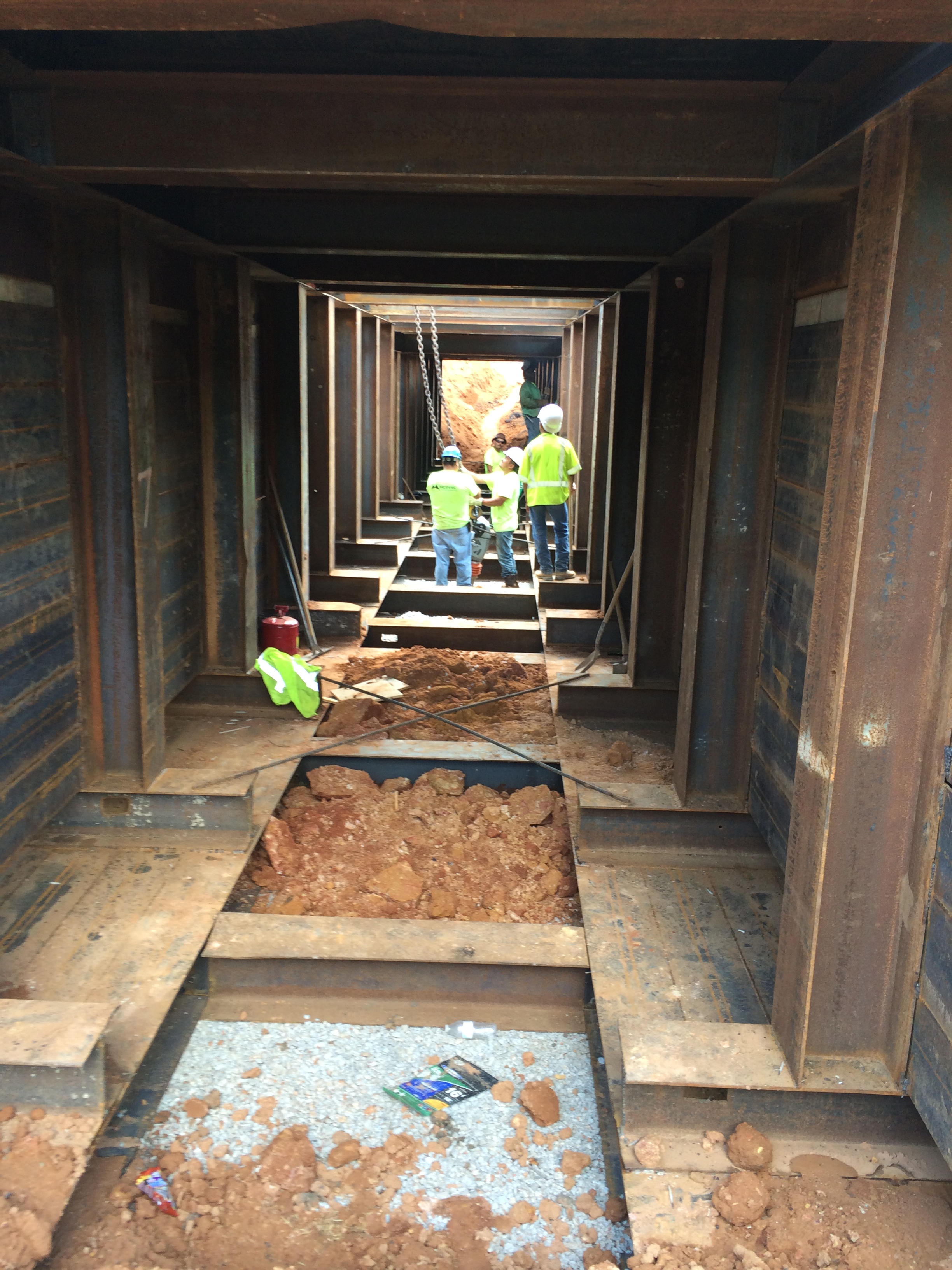
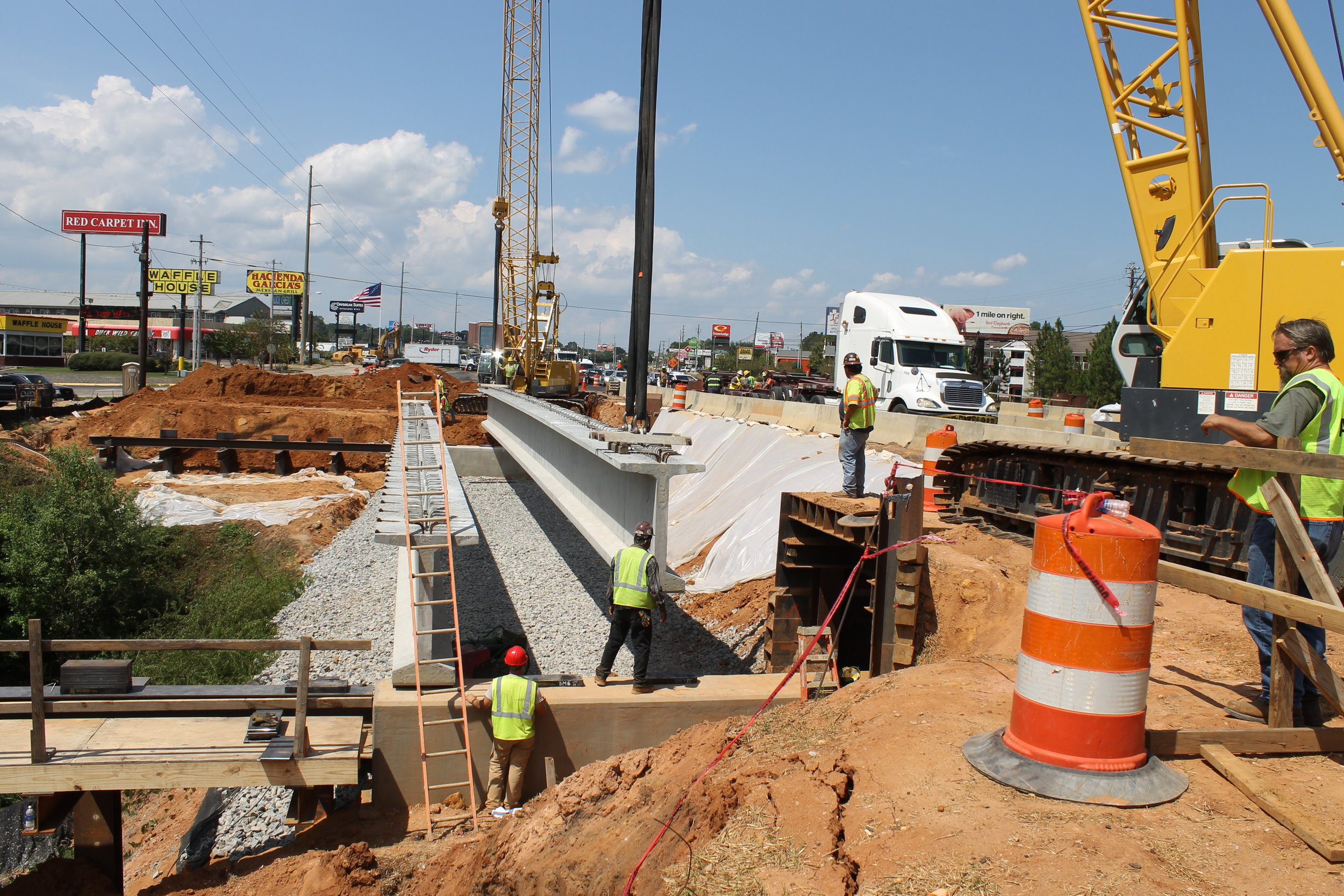
In order to keep traffic moving on Ross Clark Circle, the bridge superstructures were built adjacent to the roadway and the abutments for the single-span bridges were built under traffic. To accomplish this, steel boxes (fabricated from H-piles) were installed over a weekend and provided working space in which to build the caps. The boxes were designed to hold back the lateral soil load and support traffic loads. Once installed, the lids were removable and the contractor was able to construct the caps while traffic continued uninterrupted above. When both sub and superstructures were complete, traffic was diverted via a detour for 7 days while the soil between the abutments was cleared and the bridges were slid or rolled into place.
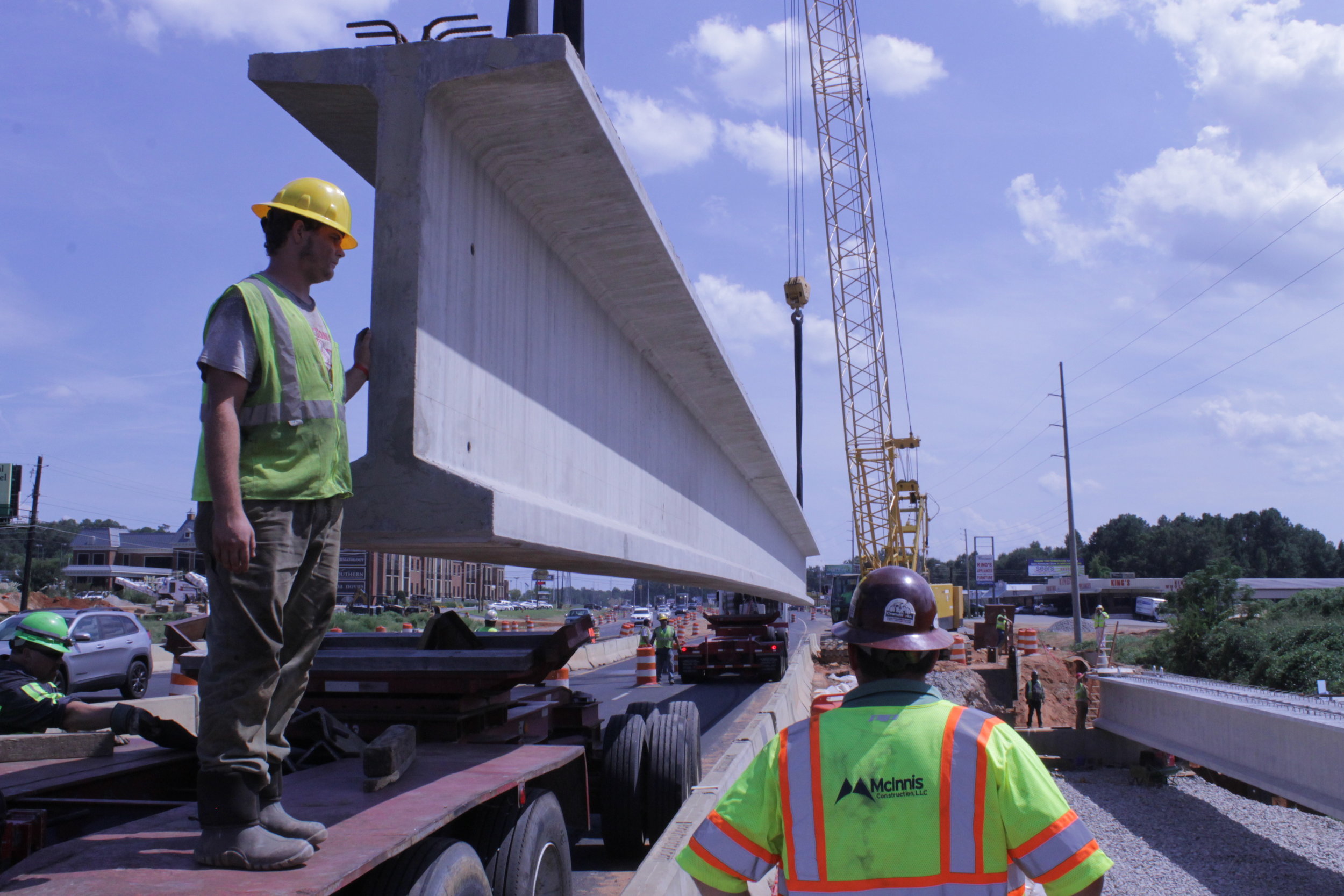
Bridge geometry and design were controlled by roadway constraints, as well as the intent to allow the bridges to be constructed using ABC principles. The southbound bridge would carry three lanes with a gutter-to-gutter width of 48 ft and the northbound bridge would carry three through lanes and one left turn lane for a total gutter-to-gutter width of 58 ft. Both bridges would be 120 ft in length. This span length was determined so that a line drawn from the bottom corner of the cap to the bottom corner of the culvert would have a slope no steeper than a 2:1 ratio, which allows for future work on the culvert.
The horizontal curve, though slight, is still enough to require the roadway and bridge deck to be in a constant 2% cross-slope. Typically, this is addressed with either pedestals or stepping the cap. In this case, neither option is suitable because the superstructure needed to be slid on a horizontal surface. The plan then was to require the girders to be placed on steel blocks or plates in order to achieve the necessary deck slope.
Alabama uses a standard abutment with cap and backwall and bridge joint between the backwall and bridge deck for conventional bridge construction. This project required something that would take considerable less time to build, especially since the abutments were to be built under traffic and the risk of racking the deck during the bridge slide and damaging a backwall was too great.
Instead, ALDOT engineers used a semi-integral abutment. Jacking bays between the girders were part of the design to facilitate the vertical jacking operations necessary to move and set the bridge. The 3-ft thickness of the diaphragm required that it be modeled using the strut-and-tie method. Using a semi-integral abutment also allowed the expansion joint to be moved between the approach slab and the lug. The lug is a pavement seat and a part of the substructure because it supports the approach slab. The lug was necessary in this project because the fill behind the diaphragm was not to be compacted and settlement was expected, leaving a gap between it and the fill. Therefore, the approach slab was designed as a one-way slab to account for this. Since thermal expansion could be absorbed by the fill behind the abutment, it alleviated the need for the contractor to compact the backfill behind the abutment, saving more time.
Although the abutment caps and superstructure were built with standard 28-day, 4 ksi concrete, the lugs and approach slab bridges would have to use a 4 ksi high-early-strength mixture. This plan, as opposed to precast concrete, was the unanimous approach taken by contractors invited to a 60% plan complete design meeting with ALDOT engineers. Additionally, the concrete for the approach slabs had to be placed and cured during the 7-day closure period
One special provision was used to guide the three aspects of ABC—the temporary shoring necessary to house cap construction, the temporary bearing supports for the superstructure during construction and sliding, and the slide/ roll itself.
The shoring design was to be provided by the contractor, engineered according to the American Association of State Highway and Transportation Officials’ AASHTO LRFD Bridge Design Specifications. Temporary supports were controlled by the latest interim edition of AASHTO’s Guide Design Specifications for Bridge Temporary Works. All aspects of the slide itself were developed from similar special provisions provided by the Utah and Iowa departments of transportation.
ALDOT bridge engineers worked toward developing a strong positive relationship with the contractor and its engineers; clarifying the objectives of the special provisions; and making suggestions that worked to the contractor’s, and ultimately the state’s, advantage. When it came time to move the bridges into place using slide in bridge construction, the contractor was fully aboard with the ABC concepts—it was able to successfully roll both bridges into place and completed the approach slabs before the end of the 7-day (per bridge) incentive/disincentive period. Traffic was returned to Ross Clark Circle over the new bridge in 3 days for the southbound direction and 3 days in the northbound direction.