
An Introduction to Precast Prestressed Concrete Insulated Wall Panels
/By Edward Losch, PhD, PE, SE, RA
Precast concrete insulated sandwich wall panels have gained popularity over the years, but some industry professionals are still not familiar with them. Reasons for their increased use in place of more traditional materials include:
Speed of erection: A typical warehouse can be erected in a week. Cold weather is not a factor, since the panels are cast in a temperature-controlled environment and shipped to the site when needed.
Design flexibility: The casting procedure allows for a great variety of finishes and patterns, including inset brick, stone and abrasive blasting.
Thermal efficiency: Edge-to-edge, top-to-bottom rigid insulation can be used within a relatively thin wall, providing a high effective R value. The thermal mass of the concrete provides an added benefit by slowing heat transmission through the wall, flattening out temperature swings. (Figure 1)

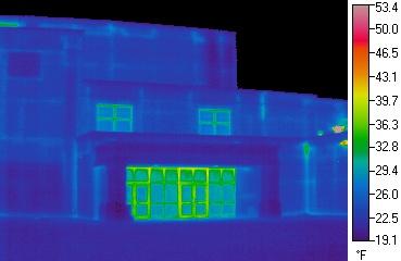
Figure 1: A thermal image of a standard “stick built” wall (left) and a precast wall (right). Blue shows areas of less thermal transference.
Used in conjunction with ASHRAE 90.1, a building’s thermal performance can actually double using precast wall elements. This in turn can reduce the size of HVAC units needed.
Competitive cost: Precast concrete wall panels can be a cost-effective alternative to masonry or other hard wall systems and does not require as much labor as other systems.
What is a precast concrete sandwich wall panel?
A typical panel has two outer concrete layers, or “wythes”, separated by rigid insulation (Figure 2), and is cast in a long-line form in a plant (Figure 3). One or both wythes are usually prestressed to reduce cracking and improve performance (Figure 4).
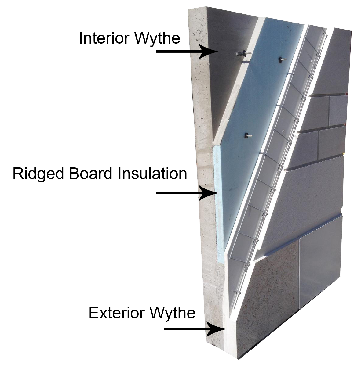

Figure 3: Placing concrete for the exterior Wythe.

Figure 4: Installing strand.
The panels are trucked to the job site and erected with a crane (Figure 5 A & B).

Figure 5a: Panels being shipped on 45-degree racks.

Figure 5b: Panels being erected using a “2 part” line.
Panels can carry roof and floor loads or just act as cladding (load-bearing vs. non-loadbearing, (Figure 6A, B and C).
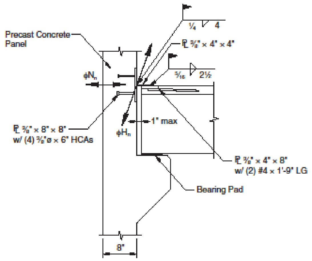
Figure 6a: Floor loadbearing.

Figure 6b: Roof loadbearing.
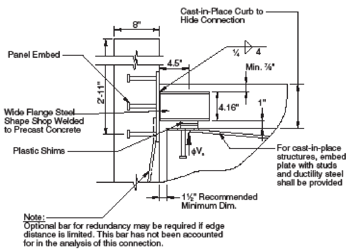
Figure 6c: Non-loadbearing wall panel connection.
Different types of panel designs
Non-composite: In non-composite panels, the concrete wythes act independently (Figure 7). This design is typically used when a high insulation value is required, such as for a cooler or freezer building. The wythes are isolated by high-performance rigid insulation and are connected together solely by thermally, non-conductive pin connectors. The pins are made of either a fiberglass and vinyl ester or polypropylene plastic or other non-conductive material. The interior structural wythe is usually much thicker than the exterior face wythe.

Fully-composite: In fully-composite panels, the wythes act together as a unit for full horizontal shear transfer. A typical composite panel is eight times stiffer, can take three times the stress without cracking and has twice the ultimate strength of a non-composite panel of similar thickness. Composite panels are typically less expensive than non-composite panels, primarily because they can carry more load and can be made taller and thinner. The inside and outside wythes are usually stressed with prestressing strand and made of equal thickness in order to minimize internal strains. (Figure 8) Sometimes, the panel is made solid below the floor line and above the parapet (outside the building envelope) to help with composite action.
Unlike non-composite panels, composite panels often bow outward when exposed to direct sunlight, due to the temperature increase and subsequent expansion of the outer wythe. This characteristic is normal but should be taken into account if panels are attached to, or butt up against, an intermediate floor near mid-height.

Partially-composite: Partially composite panels provide less than full shear transfer between wythes. They behave in a manner in-between composite and non-composite. The degree of composite action is determined by load tests performed by an independent testing lab. Proprietary partially-composite wall systems are now available which combine the high insulating value of non-composite panels with the strength and slenderness of composite panels. This is
accomplished using nonconductive truss (Figure 9), grid or individual connectors between the wythes for shear transfer. Partial composite action provides sufficient strength for most applications.

It is important to keep the distinctions between panel types in mind when determining a standard wall thickness for a project. Since the panels are cast in a form that is usually several hundred feet long, the thickness should ideally be the same for all the panels on a particular project to avoid excessive set-up costs. Occasionally, a designer will select a panel thickness based on the assumption of full composite action, but then insist on thermal performance that can only be achieved with a thicker, more expensive, non-composite design. Working with a local precast manufacturer to estimate a panel thickness can ensure design requirements are met with the most economical panel.
How are they manufactured?
Solid wet-cast: The panel face that is exposed to weather is usually cast down-in-form. The outside face, therefore, has a steel form finish. The inside face can have a float finish (rough) or hard trowel finish (smooth). Reveals and form liners can be applied to the form to add architectural interest (Figures 10 A, B and C).

Figure 10a: Ribbed formliner before casting.

Figure 10b: Reveals on the casting bed.

Figure 10c: Wood formliner texture after casting.
Projections from the face, such as a bullnose or cornice, can be cast separately and connected to the panel face later (Figure 11 A and B), or, alternately, formed out of polystyrene insulation and Dryvit.

Figure 11a: Typical “Bullnoes”.

Figure 11b: Typical Cornice.
Hollow-core wet or dry-cast: The hollow-core wythe is placed down-in-form
and is the main structural wythe for this non-composite system (Figure 12). The top wythe is thin, non-structural and serves as the outside face exposed to weather. Plastic pins or stainless steel “C” hooks anchor the top wythe to the bottom wythe. Wet-cast hollow-core uses inflatable diaphragms, insulation, or gravel to create the voids. Dry-cast hollow-core uses a zero-slump concrete mix and the “plank” is extruded from a machine-like pasta. Window and door openings are typically saw-cut in the field.

Figure 12: A standard hollowcore insulated wall panel (above) and wall panels in service at a dock location (right).
Dimensional considerations: For prestressed panels, the panel width is limited to the precaster’s long-line form width, as well as shipping restrictions. Panels more than 12 feet wide may require special handling (Figure 13), and panels wider than 14 feet can be a challenge to ship by road, due to the lane width and minimum bridge height along the chosen route. Individual panel heights are more flexible, with possible lengths of 70 feet or more. Standard flat bed trucks can carry panels up to 40 feet long, with a total cargo weight limit of 40,000 lbs. For example, a standard truck could carry two panels with a unit weight of 75 psf and dimensions of 8 feet wide by up to 33 feet long each. There is a major cost advantage to being able to ship two panels in one load, if feasible.

Figure 12: Oversized panel on a 45-degree rack.
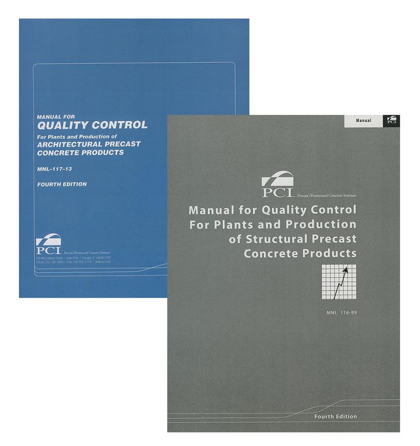
Manufacturing tolerances: Specify the Precast/Prestressed Concrete Institute Guide Specification, PCI MNL 116, “Manual for Quality Control for Plants and Production of Structural Precast Concrete Products”. Although PCI MNL 117 is the guide of choice for architectural precast products, precast/ prestressed wall panels are large and often load-bearing, so it may not be practical to meet all of the finer tolerances in MNL 117. In most cases, MNL 116 is the appropriate standard to use for this product type.
How are they designed?

Figure 14a

Figure 14b
Design responsibility: Due to the complexity of precast/prestressed concrete design and differences in standard products supplied by various precasters, the design responsibility for the precast components is usually taken by a licensed structural or professional engineer hired by the precaster. If the building has precast exterior walls only, then the lateral load calculations are usually done by the Engineer of Record (EOR). The EOR calculates and notes all loads applied to the panels on the contract structural set. The precast engineer is then responsible for the panel designs. For an all-precast building, such as a parking deck, the lateral loads may be calculated by the precast engineer. The EOR would then design the foundation only, using loads provided by the precast engineer. The design responsibilities of the precast engineer should be spelled out in the General Structural Notes to avoid conflict.
Structural planning: Use repetition to minimize the number of different forms required to produce the wall panels. Stick to a consistent panel width; 12-foot widths are usually most economical and minimize the number of vertical caulked joints. Adjust the bay spacing to match a multiple of the panel width so that
connections occur at the same place on the panels. For example, use 36- or 48-foot bays for 12-foot wide panels, and 40-foot bays for 10-foot panels. Panels with “punched” openings (Figure 14a) are easier to handle than L or C shaped panels (Figure 14b).
Anticipate the erection sequence. It is preferable for the precast concrete products to be erected all at one time. If the precast erector has to come back later to place additional panels supported by steel framing, then it may be desirable to convert this steel framing to precast. Alternately, the precast erector may be able to erect a few steel beams to avoid another “move-in”.
Handling loads may be most critical: The forces a panel experiences when stripped from the form, then bounced around on the truck to the job site and then tripped up into place, usually exceed any in-place design loads due to gravity, wind or seismic. This is a good load test for a panel; if it survives the trip, it will surely do fine in service. Lifting inserts are placed in the panel face and edges at locations designed to minimize stresses.

Brace design: For load-bearing panels, temporary steel pipe braces (Figure 15a) are usually anchored to augured or mass concrete blocks called “deadmen” (Figure 15b). Sometimes a continuous temporary strip footing is poured, and braces are anchored to them. Newer technology has been developed that uses helical anchors to secure braces. (Figure 15 C)

Figure 15a: Typical pipe braces.

Figure 15b: “Deadman” concrete block.

Figure 15c: Screw in helical anchors.
Connection design: Most precasters have a library of standard connection designs that they are comfortable with. It helps to incorporate the standard connections used by the precasters who will be bidding a particular project. Many precasters will put a clause in their contract which gives them the option to substitute
their standard connections for those shown on the structural contract set. These connections will be designed by the precast engineer. Some typical connection types are shown in (Figures 16 – 19)

Figure 16: Typical recessed panel to panel connection.

Figure 18: Typical recessed corner connection.

Figure 17: Hanging panel connections.

Figure 19: Typical panel “slip” connection.
Design software: The author has developed specialized software specifically for precast concrete sandwich wall panel design and analysis. This software has been in use since 1994 and has become the industry standard for this product type. See www.LoschSoft.com for more information.
For further information: The author recommends the Precast/Prestressed Concrete Institute report, “State-of-the Art of Precast Prestressed Concrete Sandwich Wall Panels”, 2nd Edition (Publication JR 500, available at https://www.pci.org/ItemDetail?iProductCode=JR-500). (Available as a free PDF Download)
About the author: Ed Losch is both a licensed structural engineer and architect with a PhD in Architecture from the University of Southern California. He is an active member of the Precast/Prestressed Concrete Institute (PCI) and past Chair of the PCI Precast Insulated Wall Panels Committee.
Pictures courtesy of PCI