Lake Pontchartrain Causeway
Gulf Coast Prestress Partners
Location:
Greater New Orleans Expressway Commission
Metairie, LA
Schedule:
Project Start Date: 12/17/2018
Precast Erection Start Date: 02/14/2019
Precast Erection Completion Date: 04/21/2020
Project Completion Date: 06/12/2020
Cost:
Total Project Cost: $57.5 million
Square Footage: 175,894 SF
Cost of Precast Concrete: $34.8 million
Involved Companies
Precast Concrete Producer
Gulf Coast Prestress Partners
494 Market Street
Pass Christian, MS 39571
Engineer of Record
Volkert Inc.
12777 Jones Road
Houston, TX 77070
General Contractor
Boh Bros. Construction Co.
730 S. Tonti Street
New Orleans, LA 70119
Background
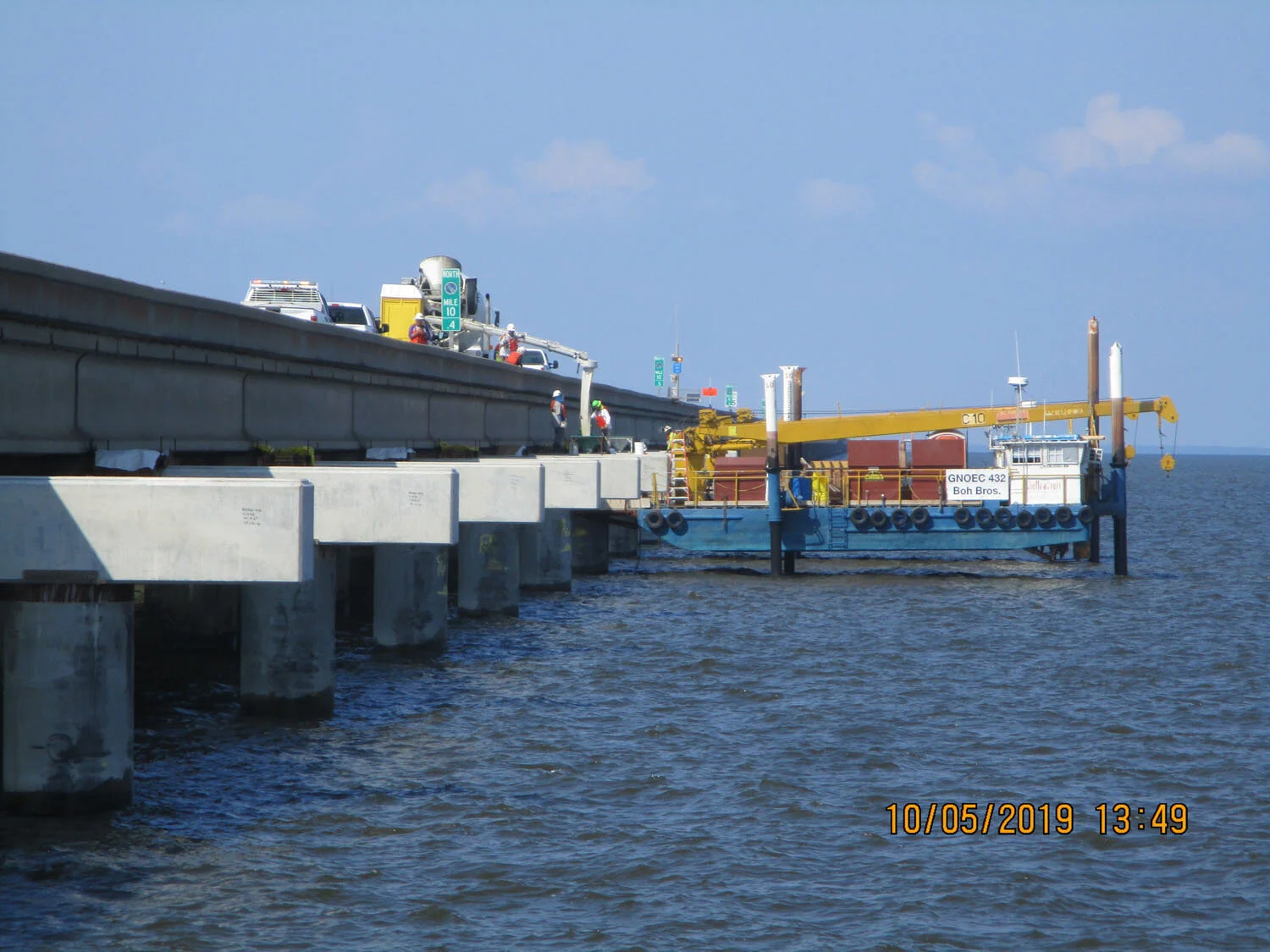
Continuous maintenance and inspections have ensured that the existing Lake Pontchatrain Causeway remained functionally sound over the years. However, with no shoulders or pullover areas, this mid-20th century bridge operating with 21st century urban traffic was becoming a safety liability. With eight to twelve breakdowns on the bridge daily and 180 crashes a year, many of them rear end collisions, the owner embarked upon a major upgrade to add twelve 1008’-long pullover lanes at multiple locations along the bridge. The improvements were the product of owner, designer and contractor collaboration under a Construction-Manager-At-Risk (CMAR) contract. With two lanes of traffic in each direction, no shoulders and over 40,000 vehicles a day, lane closures during construction were not feasible and it was necessary to minimize the duration of construction. Therefore, an all precast solution was developed – cylinder piles, pile caps and composite girder/slab deck units complete with barrier rails – with only cap-to-existing-cap and cap-to-pile connections being cast-in-place. All precast erection was performed using barge-mounted cranes for piles and pile caps and barge-mounted self-propelled modular transporters (SPMTs) for deck span unit placement, so as to eliminate operations on the deck immediately adjacent to traffic.
Challenges
Design challenges can be separated into two categories, by design phase: (1) during conceptual design, which was prior to selection of the CMAR contractor; and (2) during final design which permitted collaboration with the contractor and owner. The designer was selected by the owner on the basis of a design competition with defined “Project Performance Goals.”
The winning design met or exceeded the owner’s requirements as follows:
A cost-effective solution that was less than the owner’s proposed budget.
Added value by increasing the length of the safety bays from a previous study’s proposed length of 672’ to 1008’ per bay to improve ingress and egress lengths between the travel and pullover lanes and to increase safety for disabled vehicles and occupants within the bays.
Utilized precast concrete construction for all new bridge components so that all erection occurred from the water, thereby minimizing disruption to existing traffic and ensuring safety to both the traveling public and the workers during construction.
Other challenges during the conceptual phase of design included determination of proposed pile sizes and girder types based on locally available precast products but without knowledge of the potential contractor’s proposed equipment, means and methods. Therefore, the designer looked at both square and cylindrical prestressed concrete piles and girder types ranging from conventional AASHTO shapes to the state DOT’s newly developed prestressed I-girders and even NEXT-type double tee girders. All options were detailed in the designer’s proposal to the owner so that design could be better refined once the Construction-Manager-At-Risk was selected.
During final design the following challenges were overcome as the result of collaboration between the designer, contractor and owner:
Because the northbound and southbound structures had been built under different contracts at different times, two separate widening designs had to be developed to accommodate different span lengths and deck overhang details along the exterior edges of the bridges.
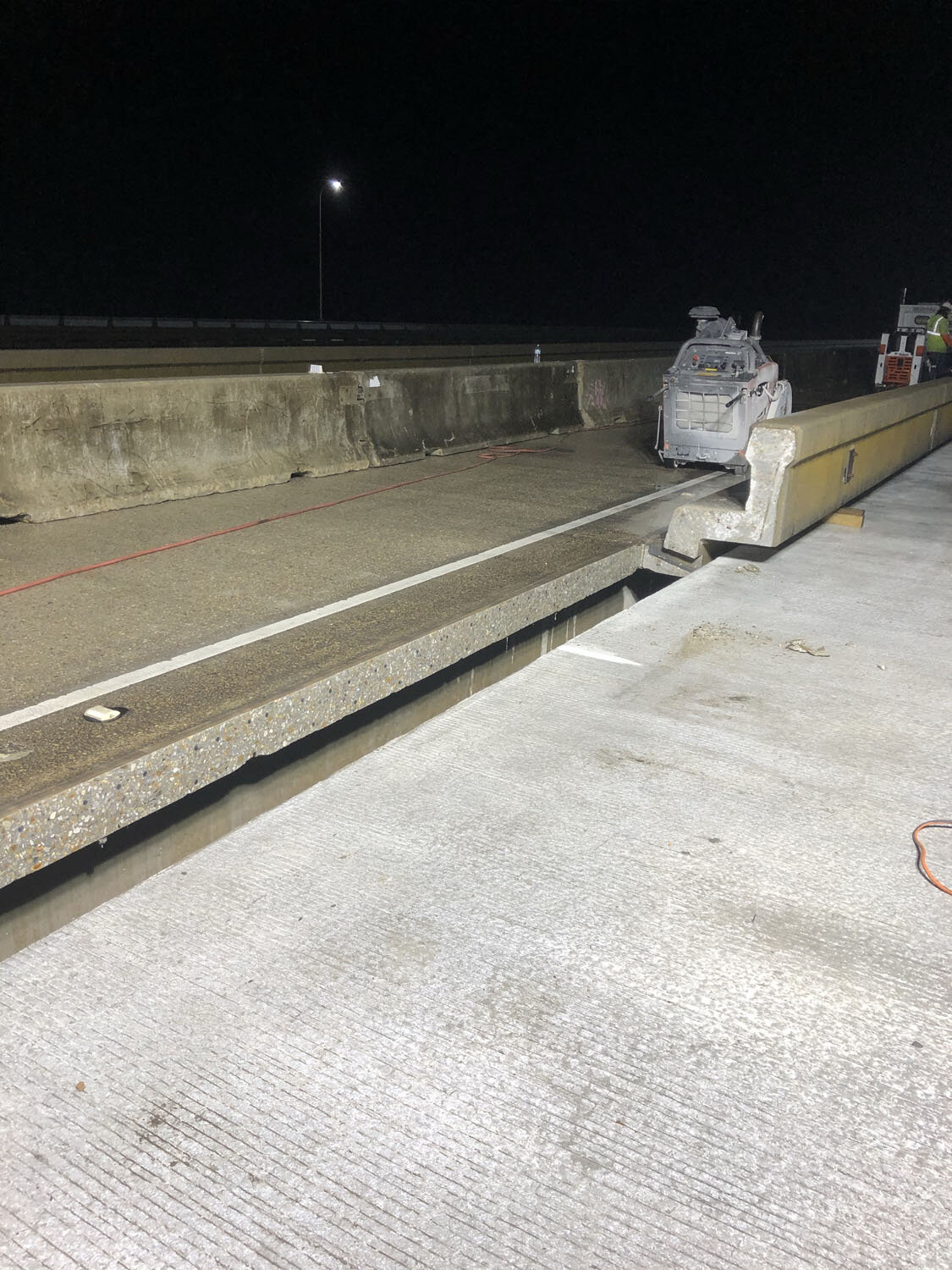
In an effort to minimize work at the deck level next to traffic, the contractor stated a preference for connecting the new precast pile caps with the existing caps instead of connecting the new deck with the existing deck overhang. This resulted in a 1” longitudinal deck joint between the existing and new pullover bay deck overhangs. Once the pile cap-to-cap connections were designed and detailed, the deck joint was fairly easily accommodated along the southbound structure since the edge of deck/tee girder flange was at the proper location for the longitudinal joint. Therefore, the new precast deck section could be slid into place next to the existing deck edge and the existing curb and barrier were removed using a horizontal cut between curb and deck top surface, all with almost no impacts to existing traffic. For the northbound structure, however, the existing deck overhang was longer, and the rail, curb and excess deck length had to be removed with a vertical cut through the deck. This necessitated lane closures at night to make the cut, grind uneven spots and then slide the new deck unit laterally the final 18” to 24” and align it adjacent to the longitudinal joint.
One final challenge involved alignment of deck units on both the northbound and southbound structures to ensure a uniform 1” longitudinal joint and an even riding surface along the joint. Over the past 60+ years, wave action from storms and minor vessel impacts have caused misalignment of a large number of the existing simple span deck units such that the deck edges were uniform in neither line nor grade. This favored the use of cast-in-place bearing seats on the precast pier caps; however, during final design the contractor opted to precast the seats with the caps so at to minimize work next to heavy traffic. Therefore, the designer included details for steel bearing shims to allow for vertical adjustments in the field. (Note: The bridge superstructure was at an elevation significantly higher than the water line and the salinity of the water body was relatively low so the long-term durability of galvanized metal shims was not a major concern.) The span geometric irregularities also required additional finishing work along the longitudinal deck joint interfaces, particularly along the northbound structure, but much of this impact was mitigated by the contractor’s method of erection (described below.)
Innovations/accomplishments
Much of the innovation and noteworthy accomplishments involving the use of precast concrete on this project were the result of the contractor’s selected methods of prefabricating the final bridge components and then erecting them. Those methods began with a solid plan that evolved with time based on discussions with the bridge owner and the designer during the final design process. Precast cylinder piles, pile caps and AASHTO girders were fabricated offsite and either barged or trucked to the project site. Piles and pile caps were installed using barge-mounted cranes and pile/bent templates. The caps were precast with 5’-long vertical bars and circular ties protruding from the bottom soffit. The caps were supported on shims on top of the 54”-diameter cylinder piles with the cage extension inserted into the pile void. A 5’-2” plug in the top of the pile was then cast through a void at the top of cap using self-consolidating concrete.
Particularly innovative were the long-line fabrication beds that the contractor set up near the bridge site in order to assemble the final deck units. The assembly lines were purpose-built along the waterfront for this project. Each of the two lines could accommodate components for one complete 1008’-long safety bay consisting of either 12 simple spans for the northbound structure or 18 simple spans for the southbound structure.
The procedure for assembly line production of the span units for each pullover bay proceeded as follows:
Cast concrete pedestals to support a pair of girders as they will be positioned in the completed span
Set precast girder pairs on the pedestals
Cast diaphragms at the ends of each span
Position permanent metal deck forms between girders and set up overhang forming on either side
Place pre-tied rebar mat on top of assembly and cast deck
Cast barrier rails on top of completed deck (including those along acceleration and deceleration transitions at either end of a bay) Using this assembly line method and setting up two lines allowed the contractor to break down the above steps to keep dedicated crews for each step continuously working somewhere along one of the lines.
Once the first line was ready for loadout to commence safety bay construction at the bridge site, the second line was already well into assembly. The first bed was then turned over to begin repeating the process for the next bay. Besides speeding prefabrication to stay ahead of erection, the long-line method also facilitated deck alignment at the bridge site. The assembly pedestals not only provided a solid foundation for assembly of the spans in the yard but also allowed for vertical adjustments using shims to ensure that the constructed spans would align with each other and would best fit the as-measured geometry of the adjacent existing deck spans over water. This was particularly critical due to the misalignment of spans that had occurred over the years from past storms and minor vessel collisions with the pier bents.
In addition to the use of assembly line construction for the bays, the contractor’s method of precast deck unit loadout onto barges and erection of the spans was also extremely innovative and best suited to meet the owner’s objectives of limiting disruptions to existing traffic and providing safety during construction. Once a complete safety bay had been fabricated in the yard, the deck units were transferred from the assembly lines to a barge using self-propelled modular transporters (SPMTs.) Each bay was loaded in reverse order so that the final span loaded would be the first one erected at the bridge site. The deck unit (with SMPTs still supporting them) were secured to the barge and all 12 spans (northbound) or 18 spans (southbound) of the safety bay were shipped to the site for erection. Although the contractor had originally planned to use barge-mounted cranes to erect the spans at the site, further discussions with the owner during the design process encouraged him to switch to SPMTs in order to construct spans from “below the rail” in order to minimize impacts, both real and perceived, to the traveling public.
With the piles, pile caps and cap connections having been previously completed for an entire pullover bay, the loaded barge was steered into position by tugs and fixed into position so that the first span in the bay could be unloaded and placed into position using the SPMTs. All final horizontal and vertical geometric adjustments were made by the hydraulic jacks on the SPMTs so that each span could be fitted exactly to the desired position in the existing structure. Once the first span was placed and positioned, the barge was moved to the next span and that deck unit was transported into place. This process was then repeated for each span until the entire bay had been erected.
After all the spans in a pullover bay had been set, it was necessary to perform a limited amount of work at deck level to remove the existing barriers and deck overhangs and properly align barriers on the precast units between spans and the 1” joint between the existing and new span units. As stated previously, this was performed without lane closures on the southbound structure, but it did require a limited number of lane closures for each pullover bay on the northbound structure. It is important to note, however, that up until this point the existing bridge rails remained in place to ensure safety for both the traveling public and the workers involved in the construction process.

High-Performance Attributes
This project could not even have been accomplished without the use of precast concrete components, which satisfied the following goals:
Minimize disruptions to the traveling public
As previously stated, the only lane closures required over the course of the 14-month erection schedule were a handful of 8.5 hour night closures per northbound bay in order to cut off the existing barrier rails and move the spans into final position. The use of SPMTs below deck level to erect span units eliminated a potential visual distraction to motorists as compared to overhead crane erection.
Ensure safety to motorists and workers during construction
Part of this was accomplished by minimizing disruptions to traffic, as described above. Another aspect was that the use of precast concrete and the selected methods of construction allowed the existing barrier rails to remain in place throughout construction, with removal only required to cut off existing deck overhangs and barriers and to permit final alignment of the bays. This served to protect both motorists and the contractor’s workforce.
Increase safety for traveling public
Construct six sets of pullover bays along the outside of each existing structure in order to increase safety for the traveling public. This was accomplished using precast concrete, and even allowed the length of each pullover bay to be increased from 672’ (as originally envisioned) to 1008’, thereby increasing acceleration, deceleration and storage lengths in the bays.
Build project within the owner’s budget
This was accomplished despite an increase in the length of the safety bays by 50% • Minimize the duration of construction. Despite 153 lost workdays due to inclement weather (i.e., rough waves, high winds, fog, heavy rain, lightning), the project was still completed in 14 months of erection time.
Photos via BOH Bros. Construction Co., LLC