SunTrust Park
Gate Precast

Location:
SunTrust Park
Atlanta, GA
Schedule:
Project Start Date: 02/02/2015
Structural Precast Erection Start Date: 08/03/2015
Structural Precast Erection Completion Date: 04/07/2016
Architectural Erection Start Date: 11/23/2015
Architectural Precast Erection Completion Date: 06/09/2016
Project Completion Date: 02/24/2017
Cost:
Square Footage: 1,200,000 SF
Cost of Precast Concrete: $14.7 million for structural precast; $8.2 million for architectural precast
Involved Companies
Precast Concrete Producer
Gate Precast
2440 South Alabama Ave
Monroeville, AL 36460
http://www.gateprecast.com
Architect
Populous
4800 Main Street
Kansas City, MO 64112
https://populous.com/
Precast Concrete Specialty Engineer
Gate Precast
2601 Cory Drive
Jacksonville, AR 72076
http://www.gateprecast.com
PCI-Certified Erector
Precision Stone
191 Pool Way
Hiram, GA 30141
Structural Engineer
Walter P. Moore and Associates
1201 Peachtree Street NE
Atlanta, GA 30361
https://www.walterpmoore.com/
General Contractor
American Builders 2017
1990 Vaughn Road
Kennesaw, GA 30144
Additional Team Member
Metromont Corporation
2802 White Horse Road
Greenville, SC 29611
http://www.metromont.com/
Additional Team Member
Consulting Engineers Group, Inc.
601 W Golf Road
Mount Prospect, IL 60056
https://www.cegengineers.com/
“The forward-thinking approach and vision for the ballpark and surrounding development will change the way we view ballpark design in the future.”
Background
A new chapter in major league baseball commenced with opening of a new stadium for the start of the 2017 season. Plans were announced to construct a new ballpark in November 2013. The team owners decided to construct a new stadium due to high infrastructure associated with upgrading/renovating the old ballpark, lack of adequate parking and the inability to develop a multi-use development surrounding the old ballpark. A sixty-acre parcel of land was located and purchased to build the new complex with fifteen acres designated for the new ballpark.
Precast concrete architectural and structural components helped achieve the designer’s goals. Due to the schedule and complexity of the project, it was a given from the beginning that the stadium seating platform and cladding would be precast concrete. Official construction began in February 2015.
In order to contribute to LEED goals, the precasters utilized regional materials produced within a 500 mile radius and incorporated recycled content, including pre-consumer and post-consumer material.
Not only was a new $672 million stadium constructed, but an entire entertainment district was developed on the adjacent property. The result created a complete environment surrounding the new stadium where people could work, live and play in addition to attending games. The stadium is the centerpiece of the new multi-use entertainment development that includes apartments, offices, restaurants and more. The entertainment complex is situated as the backdrop behind the outfield seats in the stadium.
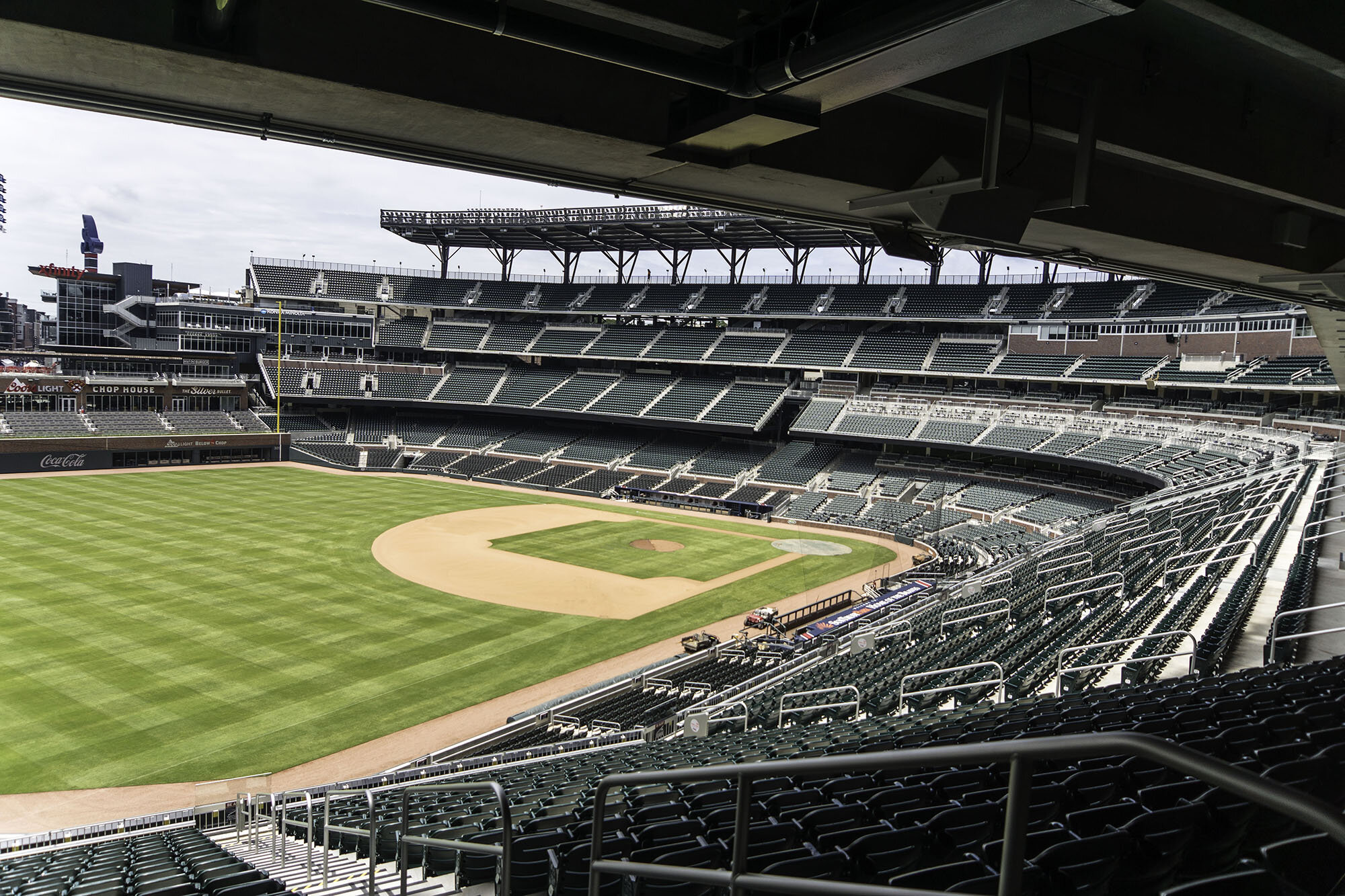
The design team focused on making the fan experience enjoyable. They studied the new innovations in recently constructed ballparks and incorporated the best features of the old ballpark into the design. There are four layers of seating starting with ground level seating snugged up close to the playing field.
The three overlapping seating decks were designed to give fans the sensation of being right on top of the action by being pushed closer to the field. Every seat faces the center of the ball field for easy, natural viewing. A cantilevered design places all the columns behind the seats and extends the front seating closer to the field than any other major league baseball stadium. The seats behind home plate are closer to the batter than the pitcher.
Seats down both foul lines are so close that batters are much less likely to foul out in this park as a foul ball quickly goes out of play.
The ballpark has a seating capacity of 41,500 with a lower level and three elevated tiers and stretches from the right field foul pole to home plate and down, and around the left field foul pole. This includes 4,000 premium seats.
The top deck is split in several locations creating openings that allow fans to view the field when on the concourse. Concourses behind the seating are wide and spacious, and facilitate moving large numbers of fans easily. In addition, all concessions and toilet facilities were moved to outer walls to provide an unimpeded view of the field.
Atop the upper deck, is a 90-feet wide canopy to ensure cover from the summer sun. The exterior façade of the stadium incorporates masonry to connect with the popular architecture of the surrounding area. In this case, thin brick was cast into architectural precast concrete panels to accelerate the project schedule. Complementing the brick veneer is precast cladding featuring a limestone color with stone detailing for a timeless look.
The home team played their first game at the new stadium mid-April 2017.
Project Details
Structural Precast Components
1009 tread-and-riser sections encompassing 225,778 ft in four depths (12”, 18”, 24”, 33”, 36”, 48” 72”) and in single, double, and triple-seat configurations were used to minimize piece counts and picks.
179 raker beams along with various columns, stairs, flat slabs, and walls.
The heaviest raker beam was 74,067 pounds.
Architectural Precast Components
555 pieces encompassing 127,377 ft, including wall panels in three finishes, spandrels, and column covers
Largest panels / heaviest: Some of the largest were 35’ 7-1/4” x 8’ – 8”, 34’ – 7 ¼” x 13’ – 7 5/8”, weighing as much as 56,000 lbs.
Unique pieces: Large C-shaped, partially brick brick-clad, column covers with very large bearing eccentricities
Many of the panels are C-shaped units twenty to thirty-five feet tall. These panels are supported vertically at their bases and laterally at their tops. Complex connections were designed to accommodate the large loads and the potential lateral movement of the support structure. These lateral movements, due to wind, thermal or seismic forces, could be in the range of one-inch or more.
Structural Finishes
Structural finishes include off-the-mold smooth finish, broom finishes and hand-trowel finishes, plus cast-in thin brick on section divider walls.
Architectural finishes include two additional finishes to complement embedded thin-brick panels, which feature three colors of brick. Some panels were cast in a buff color with a light sandblast to replicate limestone, while others have a form liner-cast appearance to replicate chiseled stone. Some brick inlay panels were used at field level to pull the exterior look inside.
The embedded thin brick is stepped out two to three times on column covers in many locations throughout the project.
Relevant Features
Improved thermal performance/reducing energy consumption
Increased open space of floor plate (e.g. reduce number of columns, obstructions, etc.)
Aesthetic versatility (helped meet the aesthetic requirements)
Improved storm resistance
Helped meet sustainability goals
Improved fire resistance
Improved safety and security to occupants
Cost-benefit
Improved blast resistance
Minimized construction site disturbance (e.g. tight site)
Increased service life/durability
Contributed to improved IEQ (e.g. no mold, no VOCs, rapid enclosure)
Structural versatility (precast used as part of the structural system)
Accelerated construction (speed of construction)
Reduced long-term life-cycle costs
Resilient design
Ultra-high-performance concrete (UHPC)
Challenges
The single most challenging design demand was the compressed schedule with no leeway on the end date permitted. To meet this requirement, the project design team used a digital project delivery process that allowed the designers to complete decisions and deadlines in short intervals. A custom set of visual programming tools and code to quickly make changes to the design model was created. This system allowed control of the complex geometry required on the project. The decision to utilize architectural and structural precast concrete was made as the result of careful consideration of its benefits to both the project design and construction. Precast concrete was the choice because of its long-term durability, costs, speed of placement and vibration control properties.
The ballpark’s location on the side of a wooded hill required significant excavation of soil and rock, with the stadium entry being 35 feet below the grade near the outfield walls. As a result, the soil height varies continuously, requiring the hybrid concrete-and-steel structural frame to be supported at the bottom of the excavation, isolated from the adjacent soil, which created intense challenges for the support of the precast concrete cladding, seating design and interiors.
Floor-to-floor heights were as tall as 35 feet in some locations, requiring brick-clad panels weighing as much as 56,000 pounds while accommodating wind and seismic loads. Erection of the massive precast panels was unique. The precast panels were erected in a particular pattern to prevent the supporting structure from distorting too much. The panels were shimmed to ensure that the joints were vertical and of a consistent width.
A small portion of the seating bowl was built on grade. In some areas, raker beams support other rakers, while others were set on solid slabs, vomitory stairs and many precast concrete elements are supported on steel beams. The entire assembly is designed as a moment frame to resist lateral loads.
Scheduling
The architectural precast production was fast-tracked to accommodate changes in the construction schedule. The project team gained ground in the CIP structure schedule, subsequently moving the erection start date up to November 2015 (originally January 2016). To support the earlier date, the architectural precast producer allocated additional engineering and plant manpower. Additionally, weekly collaboration meetings were held between the precasters, project architect, project engineer, construction manager other trades to finalize precast details.
Custom Seating Geometry Challenges
The precast seating units were ideal for the MLB ballpark due to their durability, inherent stiffness, ability to cast customized shape and the speed and ease of erection. The seating configuration in the 41,149-seat stadium differs from that of other types of sports stadiums. Baseball geometry is more random and cut up, without the standardized field layout of other sports. Seating is closer to the field even at the top levels with open sight lines, which meant varying the size of the seating risers every few levels. The seating design required fabrication of a range of structural components because of the complex geometry involved. Producing risers and tub sections to accommodate variable heights created challenges. It required new forms for every level. A more regular profile that could be repeated more frequently would have created time savings but at the cost of sight lines.
Large Steel Trusses
The architectural precast was much more than just a façade. Within the bay architecture of the exterior cladding, many different conditions exist, with a mix of straight precast panels, glazing, open mullions, louvers, entry trusses, and canopies. The precast concrete supported all of these systems.
The stadium entries feature large trusses spanning the space supported by architectural precast column panels at each end. Connecting the trusses to the precast components, and then to connecting the precast to the structure created an additional challenge and required focused coordination. The precast not only resisted the gravity, seismic and wind loading of the trusses but also the expansion and contraction forces that required special detailing and the use of teflon shims, which enabled building movements without harm to the precast façade while resisting the trusses’ vertical and lateral loads. (See Panel 4021 – Large Connection for Steel Trusses.)
Load bearing at the U-shaped columns
Large floor-to-floor spans and drift criteria of H/400 lead to drift movement in excess of 1” both in-plane. In-plane movement must allow “rocking” at the bearings, which was accomplished by high-strength, threaded rods. The configuration of the panels and very little “real estate” for connectivity to the structure necessitated the use of load-bearing connections that included a “rocking” tieback. The panels weigh ±55kips with large bearing eccentricities from the panel’s center of gravity creating formidable connections utilizing HSS shapes, headed concrete anchors (HCA’s) and weldable rebar.
Top tiebacks at the U-shaped columns
Due to the drift criteria mentioned above, connectivity of the U-shaped columns occurred at the panel returns that were as narrow as 7” in some locations. The connectivity was designed for a later force of 22.5 kips while allowing for in-plane and out-of-plane drift. The Blast PSA was chosen for connectivity. Additional reinforcement details were engineered to develop the mechanical capacity of the Blast PSA since it was not possible to do so with the PSA’s studs in only a 7” panel thickness. These reinforcement details were in the shape of U-bars extending well into the precast with auxiliary stirrups to minimize “workmanship” and ensure the U-bars were placed properly.
One item that affected both engineering and form planning was the addition of a “ledge” to some column wall panels (and some other ground level profiles) to support hand set stone in the field. Good information flow from drafting/engineering about this issue helped with planning and casting in the plant. See ticket 2019 and 2081
Innovations/accomplishments
Each field seat faces the center of the field. The cantilever design places all columns behind the seats. Due to the risers’ profile, a large majority of the seats are riser-mounted rather than tread-mounted. The prestressed concrete raker beams extend the precast concrete tread-and riser-sections closer to the playing field, which gets fans closer to the field than any other MLB Stadium. Inserts were used to support the precast concrete seating units on the rakers, avoiding the use of grout pockets that would have been exposed to view underneath and difficult to maintain. Erection of the leading-edge tub units were the most challenging and had to be set precisely. Completing a ballpark of this size in twenty-nine months from start of design to Certificate of Occupancy was a major accomplishment.
High Performance Goals Achieved
Precast concrete architectural and structural components helped to achieve many of the designer’s key goals for the stadium that serves as the focal point of the mixed used development that surrounds it. Architectural and structural precast components were the perfect choice to meet long-term durability, cost and schedule requirements.
Due to the accelerated schedule, architectural precast concrete was the superior solution for cavity wall construction, The use of architectural precast for the façade accelerated the schedule for closing in the building and eliminated the need for on-site masons and the large lay-down area in required in typical masonry construction.
The structural components, many complex and non-repetitive, fit together like a kit of parts. The use of prestressed/precast members made the cantilever design a reality giving everyone the feeling of being in the middle of the action. Precast design and production allowed other trades to complete their work on schedule.